Wlink
Wlink defines a low latency, packet based, layered architecture for communicating between two chiplets. Wlink exposes on-chip application protocols and converts these for transmission across chiplets via various physical layer implementations. Wlink acts as a protocol “pass through”. This concept of passing through the protocol versus protocol manipulation allows Wlink to remain fast, compact, and flexible.
Features
Wlink offers the following features:
Multi-lane support
Parameterizable Application Protocols
Power States
ECC/CRC Error checking
Configurable Link Settings
Various Physical Layers supported
Multi-Lane Support
Wlink provides multi-lane support. There are currently provisions for up to 256 lanes for each Tx/Rx direction. The number of lanes are not required to be powers of two (1/2/4/etc.). At compile time the maximum number of lanes is provided and during runtime the number of active lanes can be configured via SW programmability. This allows a user to reduce power by deactivating lanes when in lower power/bandwidth modes. Lane changes must be performed while the link is in a low power state or when disabled. Multi-lane support also provides the benefit that two communicating chiplets do not need to support the same number of maximum lanes, only that both chiplets have a common lane configuration.
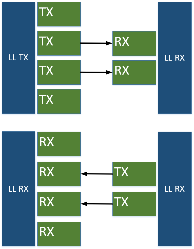
A lane mismatch where the left chiplet has four lanes and the right chiplet has two. Communication between the chiplets is still possible with both running in two lane mode.
Since chiplet communication is a tightly coupled architecture, there is no lane discovery as one would find with PCIe/DPHY. This reduces complexity and bringup time for Wlink when compared to other link protocols.
Assymetric lane support is also supported (e.g. 16Tx/10Rx). Assymetric lanes can be utilized when data profiles are heavy in one direction versus the other, potentially saving bumps and power for the application.
There are three main layers for a Wlink implementation:
Application Layer
Link Layer
Physical Layer

Wlink Layered Architecture
Each layer is designed and partitioned such that various Wlink implementations can be created and connected seamlessly. This allows various types of chiplets to be constructed and the developer can optimize the link based on the requirements of the design. For example, a user would not be required to utilize a memory mapped protocol like AXI to send transactions across (which is usually required with PCIe).
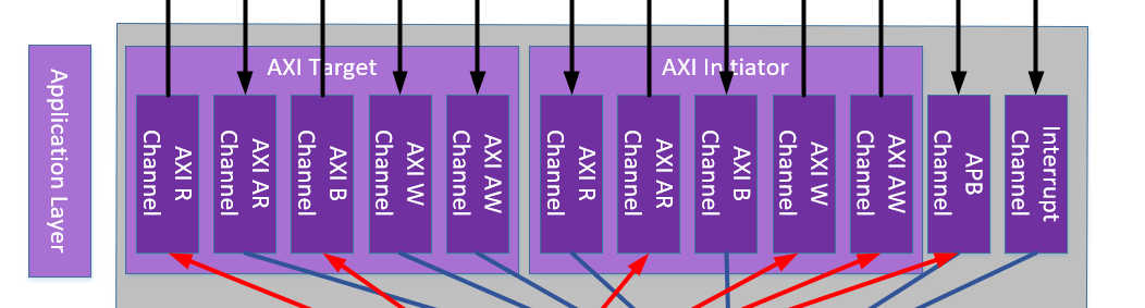
Below is a high level example Wlink implementation with an AXI, APB, and Interrupt application layer.

Wlink Example with AXI/APB/Interrupt Protocols
Most link protocols strictly define each layer, and in some cases the exact hardware for each piece. While Wlink has some predefined modules for each implementation, it allows a user to optimize various aspects for their needs. Wlink has a collection of common “nodes” that are connected to form the Wlink application and link layers.
Packet Types
Wlink uses packets to communicate between application layers on each side.
There are two type of packets in Wlink, short packets and long packets. These packet types lean heavily on the CSI/DSI packet definitions due to their simplicity as well as flexible packet lengths.
Short Packets

Short Packet Structure
Short packets are 32bits in size and are generally used for intra-link communication and small data payloads. They comprise of the following:
Data ID [7:0] - Denotes packet type
Payload [23:8] - Optional payload for short packets
ECC [31:24] - ECC used for packet error correction/detection.
Long Packets
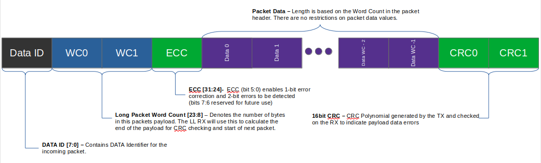
Long Packet Structure
Long Packets have varying sizes dependent on the payload size. They compromise of a 4byte packet header and 2byte CRC. The make up of a long packet is defined by the following:
Data ID [7:0] - Denotes packet type
Word Count [23:8] - Number of bytes for this long packet
ECC [31:24] - ECC used for packet error correction/detection. Same ECC as short packets
Payload - Application specific payload
CRC - CRC generated on the payload data.
Reserved Data IDs
Data ID |
Packet Type |
Payload Data |
Description |
|---|---|---|---|
0x00 |
NOP |
0 |
No Operation/IDLE packet that is used to keep the link alive but
conveys no data
|
Note
Since the calculated ECC for a NOP packet is 0 (due to data id and word count being 0), this results in no signal transitions on the data lanes when data is inactive. This assumes a link that is not encoded.
Application Layer
The application layer is the main exposed layer to the SoC/Chiplet core and converts specific protocols (AXI, APB, Tilelink, etc.) to the link layer.
Example of Application Layer Nodes
While the application layer can be thought of as a single layer, the application layer actually consists of multiple application “nodes” (e.g. APB channel above).
Each application layer node will convert a specific application protocol into Wlink packets. Each application layer also performs flow control and replayability which is discussed in WlinkGenericFCSM.
WlinkGenericFCSM
The WlinkGenericFCSM, known also as “FC block”, handles several flow control related items when communicating across WLink. It houses a generic flow control mechanism that should serve well for the majority of applications. While there may be some improvements that can be acheived by spinning your own flow control block, this provides a component for creating larger systems. Several of these can be placed for an application, with the idea being that you would use a WlinkTxRouter and WlinkRxRouter to route traffic appropriately.
The block has two conceptual directions, Application-to-Link Layer (A2L) and Link Layer-to-Application (L2A). The
data width and FIFO depth are parameters which can be chosen based on the needs of the protocol/data supported.
a2lDepth and l2aDepth represent the number of FIFO entries for the respective directions.
Note
The a2lDepth and l2aDepth values should be a power of 2 and should not exceed 128.
Each WlinkGenericFCSM will have a TX Link Layer Interface and a RX Link Layer Interface which will interface to the link layer components. The WlinkGenericFCSM is the boundary between the application layer and link layer.
Each instance of the WlinkGenericFCSM communicates with a partner instance on the far-end of the link. Each WlinkGenericFCSM is also independent of the other FC nodes. This means that if any other FC nodes were to stall due to FIFO fullness or some other application layer situation, this FC node would be able to proceed with data flow.
Using the example shown in Application Layer, if the APB Channel were to back up due to the far-end APB Channel waiting for data, the AXI Channels would still be able to proceed with data transmission.
Flow Control Training
Upon enabling the FC block, the FC will communicate with the far-end FC, exchanging information regarding the available credits for each side. Each side of the link will advertise it’s maximum TX (A2L) and RX (L2A) credits. These credits are essentially the number of available entries in each FIFO.
The link begins by sending a credit advertisement packet which is a Wlink short packet with WC0 representing the Near-End TX credits and WC1 representing the Near-End RX credits.
After recieving a credit advertisement packet, the FC block will beging to send a credit acknowledgement packet which indicates to the other side that it has received the credit advertisement.
After sending and recieving a credit acknowledgement packet, the FC block will transition to the LINK_IDLE state and wait for valid data to be transmitted.
While sending data, the transmitter keeps up with the number of available credits on the far end receiver. The transmitter is not allowed to send any packets if the reciever has no available space in the receive FIFO. Each ACK/NACK will send the current RX FIFO address back to the transmitter. This will update the transmitter and the number of available credits.
Replay Buffer
The A2L direction of the FC block includes replayability features to compensate for any link degradation resulting in loss of packets. Any time data is sent to the far end, a packet number is prefixed. This packet number is used to ensure the receiving side did not miss a packet, and the receiving side can inform the transmitting side that a packet has been missed, resulting in a replay.
During FC Training, the packet number initializes to zero and increments by one for each packet sent. When
a packet is received an ACK FC packet is scheduled to be sent. To indicate to the transmitter that the
packet was received in order, and without error. In the event a packet was either received out of order or
with an error in the packet, a NACK FC packet is scheduled with the last good packet number. Upon reception
by the transmitter of the NACK with the last good packet number, the TX will start replaying packets starting
after the last good packet number.
CRC Generation/Consumption
The CRC used in Wlink is the same version that is used in CSI/DSI. The initial seed is 0xFFFF and is reset after each long packet data payload.
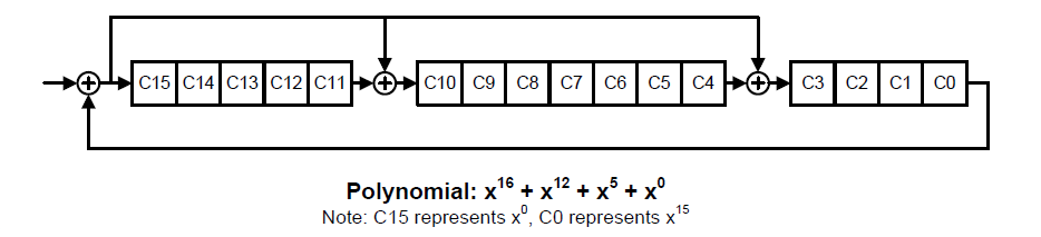
Wlink CRC Implementation
The 16bit CRC is generated for each application node in the WlinkGenericFCSM. At compile time, two WlinkCrcGen modules are created and instantiated inside each WlinkGenericFCSM. This allows the CRC to compute across the entire packet payload in a single cycle versus over multiple cycles. One WlinkCrcGen module is used to generate the CRC when transmitting a packet, and the other is to calculate the CRC on packet reception. Any CRC errors are reported to the WlinkGenericFCSM state machine.
It is possible to disable CRC checks via software register. This can be used when bandwidth is limited and the link either
Expected to be error free
The application layer can tolerate errors in the data payload
Note
Previous implementations had only one CRC generator/receiver. This implementation would work well for small designs (low numbers of lanes), but would be difficult to time as lane count grew. For this reason, the CRC generation is done per application node, which yields better timing results and in most cases yields a smaller area overhead.
For each WlinkGenericFCSM a 16bit CRC counter is available for debugging purposes. This allows a user to monitor total number of CRC errors either per node and/or for the entire link (by accumulating the CRC errors for all application nodes).
Link Layer

Wlink Link Layer Simplified Diagram
The Wlink Link Layer is responsible for the following operations
Packetizing Data
Error Detection
ECC
CRC
Error Injection
Byte Striping
Note
While data packetization and CRC generation/reception are handled in the WlinkGenericFCSM, it is still considered to be a link layer operation. The WlinkGenericFCSM acts as the boundary between the appplication and link layers.
Link Layer Interface
The Wlink Link Layer interface provides a simple hardware interface for handshaking between various link layer and applciation layer modules. There are two link layer interfaces, a TX Link Layer Interface and a RX Link Layer Interface.
TX Link Layer Interface
The Wlink TX Link Layer Interface comprises the following signals
sop- Start of packetdata_id- Data ID of the Packetword_count- Number of Bytes in the Packet (for Long Packets) / Data Payload (for Short Packets)data- Packet Data if Long Packetscrc- Calculated 16bit CRC checksumadvance- Indicates the receiving link layer node has accepted this packet
WlinkTx in the diagram above represents the TX link layer interface
RX Link Layer Interface
The Wlink RX Link Layer Interface comprises the following signals
sop- Start of packetdata_id- Data ID of the Packetword_count- Number of Bytes in the Packet (for Long Packets) / Data Payload (for Short Packets)data- Packet Data if Long Packetscrc- Calculated 16bit CRC checksumvalid- Indicates recieved data is valid for this cycle
WlinkRx in the diagram above represents the RX link layer interface
WlinkTxRouter
The WlinkTxRouter converges multiple TX Link Layer Interface bundles into a single output. The router has a simple round robin priority scheme. The priority is based on the index (the earlier an interface is attached the higher the priority), with the lowest index available having access to the link first. After link advancement, the next lowest index proceeds until no other channels have data or until the index has looped back to zero.
As an example, assume the following:
There are 3 interfaces (channels) being routed
Channel 1 and channel 2 arrive at on the same cycle
Channel 1 gains control of the link
While Channel 1 is still active, Channel 0 provides data to send
Upon advancement, Channel 2 gains control of the link
After Channel 2 advances, Channel 0 gains control of the link
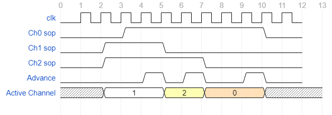
Example of channel routing
Note
Future plans involve the ability to limit bandwidth on a per channel basis
Multiple WlinkTxRouter can be cascaded if desired to limit bandwidth and/or routing channels.
WlinkTxPipeLineStage
The WlinkTxPipeLineStage is an optional link layer pipeline stage that can be used to assist with timing closure for large designs and/or when targeting higher process nodes or FPGA. A WlinkTxPipeLineStage can be inserted between any to WlinkTx compatible nodes.
WlinkTxPstateCtrl
The WlinkTxPstateCtrl monitors the Tx link layer for activity and communicates link disablement. The WlinkTxPstateCtrl uses a simple timer-based count down to observe link inactivity. After the timer has expired, the WlinkTxPstateCtrl will request the link to disable. A Pstate Request packet is sent to the other side to indicate the link is about to enter a Pstate.
Note
PState entry can be disabled by setting the timer to 0.
During PState requests, any new packets on the Tx Link Layer interface are blocked until the link has fully entered the PState. This means that once the link has started entering the PState, it cannot be stopped. The timer used to enter PState should be set based on your data profile.
Once in PState, an exit will be requested via assertion of sop on the TX Link Layer Interface.

WlinkTxPstateCtrl Simplified State Machine Diagram
WlinkTxLinkLayer
The WlinkTxLinkLayer has a single TX Link Layer Interface bundle input. It consumes WlinkTx packets and sends them to the phyiscal layer based on the number of active lanes.
ECC Generation
The Wlink ECC generation and checking implementation follows MIPI CSI/DSI ECC generation (Version 1.3 and later) which includes SEC/DED.
The inclusion ECC allows the following:
Finding if the packet header (or entire packet if short) has any errors
Checking if a single error has occurred, and if so, performing a correction
Detecting if more than a single bit error has occurred and indicating that the packet header/packet is corrupt
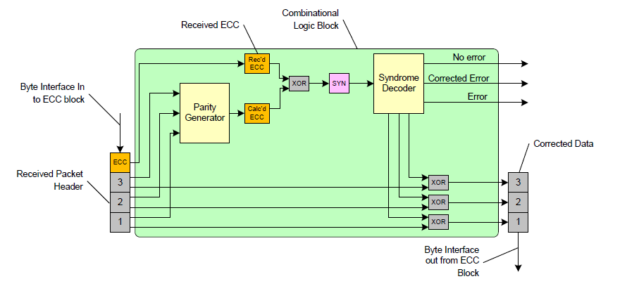
ECC Logic Block Diagram (courtesy MIPI CSI Specification)
Since ECC can correct single bit error and detect multiple bit errors, Short Packets are used for critical link communication functions such as ACK/NACKs and credit negotiations.
Byte Striping
The WlinkTxLinkLayer performs byte striping by distributing the packet across each active lane. Wlink operates on byte boundaries, so every packet sent is a multiple of 8bits. Using Long Packets as an example, the byte mapping would act as follows:
data_id- Byte 0word_count- Byte 1/2ecc- Byte 3payload- Byte 4 -> N-2crc- Byte N-1/N
When operating in a single lane, each byte is sent in order. When operating with multiple lanes active, bytes are sent in parallel. In the event a packet does not have an integer multiple of bytes based on the number of active lanes (e.g. packet length is not a modulo of 4 when in 4 lane mode) all zeros are sent as filler for the remaining lanes.
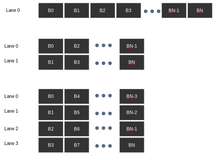
Byte Striping Example
Error Injection
The WlinkTxLinkLayer includes the ability to inject bit errors into packets prior to being sent to the physical layer. This this feature is generally used in pre-silicon testing, it is still possible to use post-silicon for additional validation as well as seeing how bit errors could affect a larger system.
The error injection works by a user programming the following
Data ID - Which data ID a user wants to cause the bit error
Byte Number - Which byte number of the packet
Bit Number - Which bit number of the selected byte to corrupt
Once programmed, the next time the respective packet is seen a bit error will be introduced. No other bit errors will be introduced until the error injection is reprogrammed.
Note
Since only a single bit error is injected the receiving ECC checker should correct this error.
WlinkRxRouter
The WlinkRxRouter broadcasts received link layer packets to all WlinkGenericFCSM nodes.
Note
Future plans involve the WlinkRxRouter to be topology aware of WlinkGenericFCSM nodes such that the router does a physical routing to the respective node on packet reception
WlinkRxPstateCtrl
The WlinkRxPstateCtrl snoops received Wlink packets to search for any Pstate Requests. If a Pstate Request is seen, it will send an indication to the physical layer to enter Pstate. During this time the physical layer shall block any further data from entering the link layer to protect against spurrious data transactions from being seen.
WlinkRxLinkLayer
The WlinkRxLinkLayer monitors the physical layer data to discover packets sent across the link. It follows the same byte striping as described in Byte Striping.
The ECC logic is the same as described in ECC Generation. However, in the WlinkRxLinkLayer the corrected packet header is sent to the rest of the link layer (the corrected packet header is used even in the case when no bit errors were detected).
ECC corrections and corruptions are captured and sent to interrupts for debugging purposes.
There is an optional feature in the WlinkRxLinkLayer where on ECC corruption (more than 1bit error in packet header) the link layer can place itself in an ERROR state, ignoring all future link data. This can be used to keep the application layers in a steady state until the link degredation issues have been resolved (e.g. a retrain is required). This feature defaults to enabled, and can be disabled via software register.
Physical Layer Support
The Wlink is designed in such a way that the the link layer and physical layer are not tightly coupled. This allows multiple physical layers to be used with Wlink. Most high performance implementations of Wlink utilize a high speed die-to-die (D2D) running at 28Gbps/lane. However for some low bandwidth applications and/or prototyping on FPGA, Wlink can communicate with a simple GPIO/LVDS based SerDes. Future plans include the ability to have Wlink operate with an Intel AIB compatible PHY, as well as with a traditional PCIe based PIPE PCS/PHY.
For each implementation, a gasket may be created depending on the complexity of the PHY. For example, for PIPE based PHYs, some portions of the PCIe/USB LTSSM need to be performed for initial PHY bringup. The details of this are outside the scope of this document.
Even though Wlink sends Pstate requests, the link is only aware of enabled/disabled states. The reasoning behind this is the link either has data to send or it does not. When the link is inactive, any power savings should be utilized when possible. Since power states are highly dependent on the physical layer and it’s implementation, the definition of power states is left to the physical layer implementation. For example, a GPIO/LVDS based PHY could simply stop sending a clock when the link is inactive, and resume the clock on activity. A PCIe PIPE based PHY would not have this luxury and would require a more complex link enablement routine.
Since the Pstate functionality is pushsed into the physical layer, each physical layer implementation is free to utilize the most appropriate PState settings for it’s own implementation.