Wlink PHY Wrapper
One significant down fall of traditional Verilog designs is the inability (or extreme difficulty) to
allow various modules to be used for a particular portion of the design. `ifdefs and generate
statements are the usual go-to however they quickly begin to deteriorate as the design changes or
complexity is added.
To combat this issue, the Wlink PHY provides a “PHY Wrapper”. While at first this may sound like
a traditional Verilog wrapper, the features provided quickly beging to show the differences. A
WlinkPHYBase class is provided which defines the main Bundles/interfaces of the PHY, but the user
has the option to have their own custom interfaces depending on the PHY type.
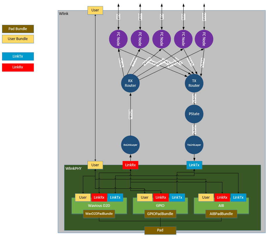
Wlink diagram showing the possibility of mulitple PHYs (note only one PHY at a time is possible)
Link2PHY Bundles
The link2phy bundles are required for each PHY implementation. A PHY is not allowed to change these interfaces and must support the features of each. Thankfully, the link2phy interfaces are simple in nature and only have a few basic requirements.
class WlinkPHYTxBundle(val linkDataWidth: Int) extends Bundle{
  val tx_en               = Input (Bool())
  val tx_ready            = Output(Bool())
  val tx_link_data        = Input (UInt(linkDataWidth.W))
  val tx_data_valid       = Input (Bool())
  val tx_active_lanes     = Input (UInt(8.W))
  val tx_link_clk         = Output(Bool())
}

class WlinkPHYRxBundle(val linkDataWidth: Int) extends Bundle{
  val rx_enter_lp         = Input (Bool())
  val rx_link_data        = Output(UInt(linkDataWidth.W))
  val rx_data_valid       = Output(Bool())
  val rx_active_lanes     = Input (UInt(8.W))
  val rx_link_clk         = Output(Bool())
}
Signal Name |
Description |
|---|---|
tx_en |
0 - Transmitter can be disabled (no data from link layer)
1 - Transmitter should be enabled (data to send from link layer)
|
tx_ready |
0 - Transmitter is not ready to send data
1 - Transmitter is up and sending data
|
tx_link_data |
Link data to send. Should be updated on every cycle in which tx_ready
is asserted
|
tx_data_valid |
Currently un-used |
tx_active_lanes |
Per lane signal used to indicate that lane should be active. This signal
should only be changed when the link is disabled
|
tx_link_clk |
Link clock for TX link layer logic. In cases where the transmitter(s)
are inactive, this clock should be kept running (even if lower freq) for
link layer logic to see new packets and signal a wake up event for the
transmitters
|
Any time
tx_enis deasserted it shall wait for deassertion oftx_readyprior to reassertingtx_enThere is currently no requirement on transmitter enablement time.
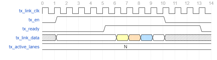
Example WlinkPHYTxBundle enabling the transmitter, sending data, then disabling
Signal Name |
Description |
|---|---|
rx_link_data |
Link data received. Valid only when |
rx_data_valid |
Indicates receiver data is valid for this cycle |
rx_active_lanes |
Per lane signal used to indicate that lane should be active. This signal
should only be changed when the link is disabled
|
rx_link_clk |
Link clock for link layer logic. This clock can be gated when the
receiver is not active.
|
rx_enter_lp |
Indicates the link layer RX has received a Pstate request. This
signal will assert for a single
rx_link_clk cycle everytimea Pstate request is seen.
|
There is currently no requirement on receiver disablement time.
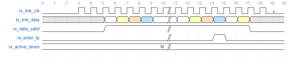
Example WlinkPHYRxBundle being enabled, receiving data, and later disabling
Note
Pstate requests are generally handled by the WlinkTxPstateCtrl block and are
sent after link data has quiesced. Due to this, there should be no valid link data
after a Pstate request is seen and rx_enter_lp has been asserted. See WlinkTxPstateCtrl
for more details
WlinkPHYBase
The WlinkPHYBase is a base level LazyModule that a User would extend from to create their
own PHY wrapper for Wlink integration. Any PHY implenataion should extend from WlinkPHYBase.
There are a handful of interfaces that are defined and required when integrating ones own PHY.
Below is a list of the interfaces
Interface/Signal Name |
Customizable? |
Description |
|---|---|---|
scan |
N |
DFT Scan. Not required for use |
por_reset |
N |
Power on reset. Not required for use |
link_tx |
N |
|
link_rx |
N |
|
user |
Y |
User customizable |
pad |
Y |
User customizable |
The reason for these signals being a requirement is simply to have a common handle at the Wlink Module in which
the PHY is instantiated since the user and pad bundles are cloned and auto connected at the next level.
abstract class WlinkPHYBase()(implicit p: Parameters) extends LazyModule{

  // APB Identity Node for APB connections
  // (this produces no logic and is only for connecting at a higher level)
  val node        = APBIdentityNode()

  lazy val module = new LazyModuleImp(this) with RequireAsyncReset{
    val scan      = new WavScanBundle             //DFT Scan (a User can set this as dontTouch if not using)
    val por_reset = IO(Input (Bool()))            //Power on reset
    val link_tx   = IO(new WlinkPHYTxBundle(8))   //Link2PHY
    val link_rx   = IO(new WlinkPHYRxBundle(8))   //Link2PHY

    val user      = IO(new Bundle{})              //User Customizable
    val pad       = IO(new Bundle{})              //PAD Customizable
  }
}
WlinkPHYBaseParams
The WlinkPHYBaseParams are the base class for WlinkPHY Parameters and contain the minimum subset of parameters
needed for proper Wlink construction. Below is an explanation of each parameter
Parameter |
Description |
|---|---|
phyType |
PHY Generation function |
numTxLanes |
Number of Tx Lanes |
numRxLanes |
Number of Rx Lanes |
baseAddr |
Base address of the PHY |
phyDataWidth |
Data Width of each PHY lane |
phyVersion |
32bit numerical value to represent the specific PHY type (only used for
informational purposes)
|
phyVersionStr |
String value to use in the phyVersion register description (only used
for informational purposes)
|
abstract class WlinkPHYBaseParams{
  def phyType       : (Parameters) => WlinkPHYBase
  def numTxLanes    : Int
  def numRxLanes    : Int
  def baseAddr      : BigInt
  def phyDataWidth  : Int

  def phyVersion    : UInt
  def phyVersionStr : String
}
Note
The parameters you see in WlinkPHYBaseParams have not been defined, so the case class you create for your
own implementation must define these. This is because they are used by the Wlink components to build various
portions of the link controller that connect to the PHY.
GPIO Example
Here I have a simple GPIO Based PHY that I want to use with Wlink. In this case, the PHY has N Tx and M Rx lanes. It uses
a WavD2DGpioBumpBundle for representing the bumps/pads. It utilizes the standard scan, por_reset, link_tx,
and link_rx bundles. I do need one additional signal that is not included in the base PHY. This signal is a hsclk
signal which is the root serial clock for highspeed transmission and generates the link clock for the link_tx logic. Since
this signal is specific to this phy type and isn’t a pad signal, this becomes a good candidate for a custom user bundle.
Here I have created a WlinkGPIOPHYUserBundle. In this case, it only contains the hsclk signal that is needed.
class WlinkGPIOPHYUserBundle extends Bundle{
  val hsclk   = Input (Bool())
}
The user bundle is not limited to just individual signals. You can include sub-Bundles inside, giving you a cleaner interface. Here is a possible example where I have a boundary scan bundle and a refclk in my user bundle.
class WlinkMyBSRRefclkUserBundle extends Bundle{
  val bsr             = new WavBSRBundle
  val refclk_ana_in   = Input (Bool())
}

//....
// Getting the tck in the PHY
my_tck_reference := user.bsr.tck
Note
In the event you don’t have any user signals, you will still need to include a user Bundle, but it can be an empty bundle as seen below. In this case, no signals are generated in the RTL.
val user = IO(new Bundle{})
The WlinkPHYGPIOExampleParams show an example of the types of parameters a user may create for their respective PHY. We are required
to define the values presented in WlinkPHYBaseParams but we also have the ability to add custom parameters for our own PHY
implementation.
For example, here we have a parameter someCustomParam. Minus the super original name, it doesn’t really do much other than print
out a message during generation, but if you notice this parameter isn’t in the WlinkPHYBaseParams. You aren’t limited to the
number of extra parameters, so you are free to be as creative as you want. As an example, let’s say you want to create a phy which is LVDS
based. You target multiple FPGA vendors, who each have different names for their LVDS cells. One could create a parameter that
gives the LVDS cell or vendor.
Here is what the WlinkPHYGPIOExampleParams look like when implemented.
case class WlinkPHYGPIOExampleParams(
  phyType       : (Parameters) => WlinkGPIOPHY = (p: Parameters) => new WlinkGPIOPHY()(p),
  numTxLanes    : Int = 1,
  numRxLanes    : Int = 1,
  baseAddr      : BigInt = 0x0,
  phyDataWidth  : Int = 16,
  phyVersion    : UInt = 1.U,
  phyVersionStr : String = "GPIO",

  someCustomParam: String = "Making a GPIO PHY"

) extends WlinkPHYBaseParams
Whoa, what is phyType you have shown me? This is a scala call-by-name parameter. If you’re new to scala or Chisel, come back to this
after some time. For now, just know that you define the Module class to call this way. If you create your own custom version here
is what you would want to replace
phyType       : (Parameters) => WlinkGPIOPHY = (p: Parameters) => new WlinkGPIOPHY()(p),
//                              ^Your Module                          ^Your Module
WlinkGPIOPHY is the actual implementation of the PHY top level we wish to use. As shown, we extend from WlinkPHYBase.
Below is an example for the WavD2DGpio version with explainations on each section of the code
class WlinkGPIOPHY()(implicit p: Parameters) extends WlinkPHYBase{

  // Get the params from the CDE since we will use them in the
  // instantiation
  val params  : WlinkPHYGPIOExampleParams = p(WlinkParamsKey).phyParams.asInstanceOf[WlinkPHYGPIOExampleParams]

  // "Instantiate" the WavD2DGpio Module
  // Here we use the term "instantiate" loosely as this is a LazyModule
  // and we don't have access to the IOs at this level.
  val gpio    = LazyModule(new WavD2DGpio(numTxLanes=params.numTxLanes,
                                          numRxLanes=params.numRxLanes,
                                          baseAddr=params.baseAddr,
                                          dataWidth=params.phyDataWidth)(p))

  // Connect the APB Identity Node to our APB node in the gpio cell
  // This connection simply draws a node connection.
  gpio.node   := node

  // Printing our custom parameter. This is just for show
  println(params.someCustomParam)

  // Creating the actual module implementation of the ``WlinkGPIOPHY``
  override lazy val module = new LazyModuleImp(this) with RequireAsyncReset{

    //  Defining our bundles
    val scan      = IO(new WavScanBundle)
    val por_reset = IO(Input (Bool()))
    val link_tx   = IO(new WlinkPHYTxBundle(params.numTxLanes * params.phyDataWidth))
    val link_rx   = IO(new WlinkPHYRxBundle(params.numRxLanes * params.phyDataWidth))

    // Notice how we include our own BumpBundle?
    val pad       = IO(new WavD2DGpioBumpBundle(params.numTxLanes, params.numRxLanes))

    // And we do the same for the user bundle
    val user      = IO(new WlinkGPIOPHYUserBundle)

    // Now we connect up everything to the gpio instance
    // Since the WavD2DGpio is a LazyModule, don't forget that you need to
    // reference the gpio.module!
    gpio.module.io.por_reset   := por_reset
    gpio.module.io.hsclk       := user.hsclk
    gpio.module.io.link_tx     <> link_tx
    gpio.module.io.link_rx     <> link_rx
    gpio.module.io.pad         <> pad
    gpio.module.io.scan.connectScan(scan)

  }
}
Wow, that seems like a lot of setup just to instantiate a cell!
At first glance, you would not be mistaken, however think about how this would be done in a Verilog design (if it could even be done in a Verilog design). Hopefully after seeing the power of this method, you see the elegance in it. The goal is to provide a way for the user to easily plug in a specific PHY of their own and/or to select from various PHYs that we plan to produce as open source in the future.
Using Non-Chisel Based PHYs
If you have a PHY design that you would like to try out but it is written in Verilog/VHDL don’t fret! The nice thing about Chisel is that it does support Verilog integration with BlackBoxes.
The only thing you would need to create is the LazyModule wrapper that we have shown above.